RESEARCH AREAS
– Dimple Array on Surfaces of Channels
– Investigations of Confined, Millimeter-Scale, Unsteady Laminar Impinging Slot Jets
– Aerodynamic Losses and Mixing Losses from Turbine Airfoils
– Impingement Cooling
– Internal Cooling – Surface Heat Transfer Augmentation
– Miniature and Micro-Scale Pumps
– Surface Roughness
– Electronics Cooling
– Transitional Flows in Curved Channels
– Film Cooling
– Flow and Heat Transfer on and Near a Transonic Turbine Blade Tip
– Slip Phenomina in Micro-Fluidic Devices
– Buoyancy-Driven Continuous SPLITT Fractionation: A New Technique for Separation of Microspheres
– Investigations of Full-Coverage Film Cooling
– Shock Wave Boundary Layer Interactions
– Double Wall Cooling
– Elastic Turbulence
– Surface Roughness Effects on Impingement Jet Array Surface Heat Transfer
– Dean Flow Dynamics in Low-Aspect Ratio Spiral Microchannels
Double Wall Cooling
DOUBLE WALL COOLING INVESTIGATIONS – INTERNAL AND EXTERNAL COOLING OF A FULL COVERAGE EFFUSION COOLING PLATE: EFFECTS OF DOUBLE WALL COOLING CONFIGURATION AND CONDITIONS
Overall, the project utilizes a facility which is designed to provide full coverage film cooling heat transfer data and internal passage heat transfer data, wherein the film cooling flow is supplied using either cross flow 1,2,3,4, impingement flow 5,6, or a combination of both together. The experimental facility uses three independent flow channels to provide double wall cooling arrangements which model configurations from combustor liner components of gas turbine engines. Streamwise hole spacing and spanwise hole spacing (normalized by effusion hole diameter) on the effusion plate are 15 and 4, respectively. As such, a sparse effusion hole array is utilized. Effusion hole diameter is 6.35 mm, effusion hole angle is 25 degrees, and effusion plate thickness is 3 hole diameters. Considered are overall effusion blowing ratios from 2.9 to 7.5, with subsonic, incompressible flow. As such, the effusion film is turbulent for all experimental conditions investigated. Note that velocity of the freestream flow which is adjacent to the effusion cooled boundary layer can be set to be approximately constant with streamwise distance, or can be set to increase with streamwise distance, as a result of a favorable streamwise pressure gradient. The data presented here are all obtained with freestream flow velocity which is approximately constant with streamwise distance.
A side, cross-sectional view schematic diagram of the experimental facility is shown in Figure 1, including optical instrumentation arrangements. Research efforts are aimed at securing new experimental data for both the hot/mainstream side, and the cold/cross flow side of the effusion plate. Two mesh heaters are used to provide a near instantaneous step-change in mainstream flow temperature, after all flow conditions are established. For the effusion cooled/hot surface, presented are spatially-resolved distributions of surface adiabatic film cooling effectiveness, and surface heat transfer coefficients (measured using transient infrared thermography) 1-6. For the coolant/cross flow/impingement cooled side, presented are spatially-resolved distributions of surface Nusselt numbers (measured using steady-state liquid crystal thermography) 1-6. Of primary interest are the effects of coolant supply flow conditions, effusion blowing ratio, streamwise development, and mainstream Reynolds number.
Coolant Supplied Using Cross Flow Channel
Figures 2 through 7 are obtained using coolant supplied with cross flow channel only. The present data are provided for a main flow Reynolds number of about 95000. Five different crossflow Reynolds numbers are tested, which are associated with five different values of overall blowing ratio BR. For the hot side (mainstream) of the effusion film cooling test plate, Figure 2 shows that the adiabatic cooling effectiveness increases just downstream of holes due to local accumulation of coolant along the test surface. Figure 3 shows that higher heat transfer coefficient values are generally observed just upstream and around the holes. Lower heat transfer coefficient values are observed away from the holes. Figures 4 and 5 show that line-averaged adiabatic film cooling effectiveness generally increases, and line-averaged heat transfer coefficient also generally increases, as the blowing ratio becomes larger, when compared at a particular streamwise location x/de. and mainstream Reynolds number 1-4.
For the cross flow cooled side of the effusion plate, Figure 7 shows that streamwise varying line-averaged Nusselt numbers increase with blowing ratio, when compared at a particular streamwise location x/de, and main flow Reynolds number. This is a result of associated increases of cross flow Reynolds number. Increases of local and line-averaged Nusselt numbers also occur in the vicinity of effusion hole entrances, as illustrated by data presented in Figures 6 and 7. Such behavior is due to increases of local flow advection speeds as cross flow fluid approaches and then enters into effusion hole entrances 1-4.
Coolant Supplied Using Impingement Jet Array
Figures 8 and 9 are obtained using coolant supplied with an impingement jet array only. The present data are provided for a main flow Reynolds number of 142,000-155,000. Five different impingement jet Reynolds numbers are tested, which are associated with five different values of overall blowing ratio BR. The associated experimental data are given for a ratio of jet-to-target plate distance to effusion hole diameter of 14, impingement plate thickness of 3.0 effusion hole diameters, and spanwise and streamwise impingement hole spacing such that coolant jet hole centerlines are located midway between individual effusion hole entrances 5-6.
Examples of spatially-resolved experimental results are given in Figures 8 and 9. Figure 8 provides a comparison of local, spatially-resolved surface Nusselt number variations for the coolant / cross flow side of the effusion plate, for different blowing ratios for a mainstream Reynolds number of 142,000-155,000. Here, data are given for blowing ratio BR values of 3.3, 4.3, 5.5, 6.3, and 7.4. Note that normalized streamwise location x/de = 0 is defined at the upstream edge of the area of present spatially-resolved measurements. Here de is the effusion hole diameter. Also included within Fig. 8a are locations of the impingement holes as well as the effusion hole entrances 5-6.
According to the results within Figure 8, regardless of the value of blowing ratio BR, the highest local Nusselt numbers are present at smaller x/de locations, relative to the locations of the impingement hole centerlines. Such Nusselt number augmentation regions are associated with impingement jet stagnation locations, which are positioned at different x/de locations, relative to the impingement holes. This is because of turning and re-direction of the impingement jets as they cross the impingement passage. The re-direction is a result of the static pressure variations within the passage, with lowest values near the entrances of the effusion holes. With this physical situation, coolant within impingement jets exits the impingement holes, turns to smaller x/de locations, and then impacts upon the coolant side of the effusion plate. Afterwards, the coolant is then re-directed along the plate surface. Afterwards, it enters into individual effusion holes, which are also located at smaller x/de locations, relative to adjacent impingement hole locations 5-6.
Figure 9 gives surface, local heat transfer coefficient variations in dimensional form for BR=7.4 and a mainstream Reynolds number of 142,000. Here, heat transfer coefficients range from approximately 20 W/m2K to 140 W/m2K along the test surface. Higher heat transfer coefficient values are generally observed just upstream, around, and along a trajectory downstream of each hole. Lower heat transfer coefficient values are generally present away from the holes. These variations are tied to jet mixing, vortex development around jet coolant concentrations, increased shear near jet edges, and the resulting augmentations of local three-dimensional turbulent transport 5-6.
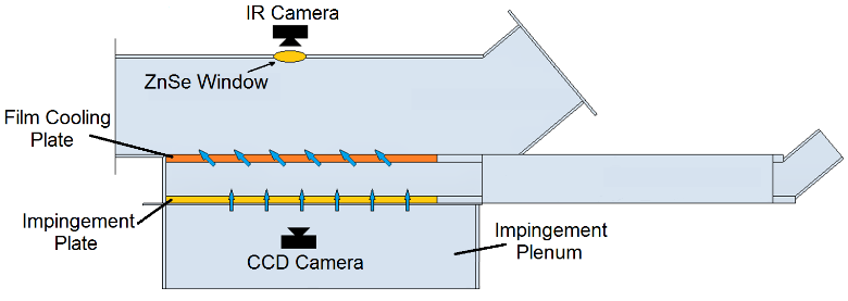
Figure 1. Side, cross-sectional view of the test section, including optical instrumentation arrangements.
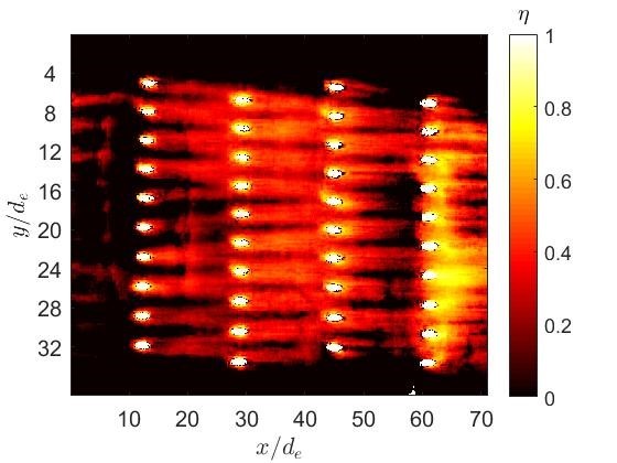
Figure 2. Local, spatially-resolved surface adiabatic film cooling effectiveness distribution with mainflow velocity of 5 m/s, with a Reynolds number of around 97267, a mainflow temperature of 306 K, and a blowing ratio of 3.4. Data provided for mainstream, hot-side of effusion cooling test plate.
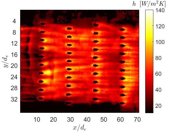
Figure 3. Local, spatially-resolved surface heat transfer coefficient distribution with main flow velocity of 5 m/s, with a Reynolds number of around 93642, a mainflow temperature of 307 K, and a blowing ratio of 5.5. Data provided for mainstream, hot-side of effusion cooling test plate.
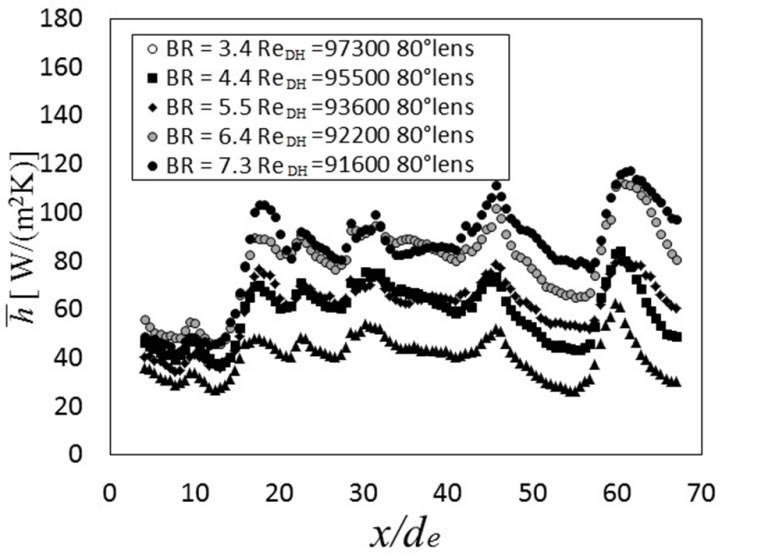
Figure 4. Streamwise variation of line-averaged heat transfer coefficient with main flow velocity of 5 m/s, with a Reynolds number of around 95000, main flow temperature of 307 K, and the blowing ratios of 3.4, 4.4, 5.5, 6.4, and 7.3. Data provided for mainstream, hot-side of effusion cooling test plate.
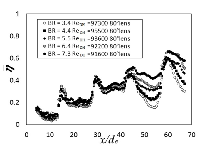
Figure 5. Streamwise variation of line-averaged adiabatic film cooling effectiveness with main flow velocity of 5 m/s, with a Reynolds number of around 95000, main flow temperature of 307 K, and the blowing ratios of 3.4, 4.4, 5.5, 6.4, and 7.3. Data provided for mainstream, hot-side of effusion cooling test plate.
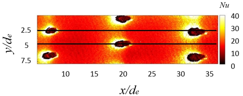
Figure 6. Local, spatially resolved Nusselt number distribution with mainflow velocity of 5 m/s, main flow Reynolds number of approximately 95,000, crossflow temperature of 294 K, and blowing ratio of 3.4. Data provided for cross flow, cold-side of effusion cooling test plate.
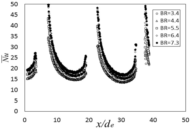
Figure 7. Streamwise variation of line-averaged, spatially resolved Nusselt number for different blowing ratios with mainflow velocity of 5.1 m/s, main flow Reynolds number of approximately 95,000, and crossflow temperature of 294 K. Data provided for cross flow, cold-side of effusion cooling test plate.
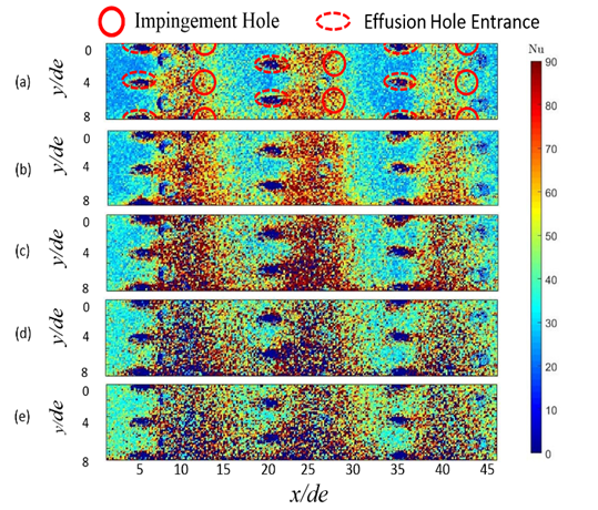
Figure 8. Comparison of local, spatially-resolved surface Nusselt number variations for cold side of effusion plate for different blowing ratios BR and mainstream Reynolds number of 142,000-155,000. (a) BR=3.3. (b) BR=4.3. (c) BR=5.5. (d) BR=6.3. (e) BR=7.4.
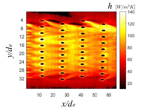
Figure 9. Surface, local heat transfer coefficient variation for hot side of effusion plate for BR=7.4 and mainstream Reynolds number of 142,000.
RECENT PUBLICATIONS
- Effects of Double Wall Cooling Configuration and Conditions on Performance of Full-Coverage Effusion Cooling, (N. Rogers, Z. Ren, W. Buzzard, B. Sweeney, N. Tinker, P. M. Ligrani, K. D. Hollingsworth, F. Liberatore, R. Patel, S. Ho, and H.-K. Moon), ASME Transactions-Journal of Turbomachinery, Vol. 139, No. 5, pp. 051009-01 to 051009-13, May 2017.
- Internal and External Cooling of a Full Coverage Effusion Cooling Plate: Effects of Double Wall Cooling Configuration and Conditions (Z. Ren, S. R. Vanga, N. Rogers, P. M. Ligrani, K. D. Hollingsworth, F. Liberatore, R. Patel, R. Srinivasan, and Y.-H. Ho), International Journal of Thermal Sciences, Vol. 124, pp. 36-49, February 2018.
- Vortex Structure Effects on Impingement, Effusion, and Cross Flow Cooling of a Double Wall Configuration (P. M. Ligrani), Journal of Physics: Conference Series, IOP Science Publishing Corp., Vol. 980, pp. 012018-1 to 012018-15, March 2018
- Double Wall Cooling of a Full-Coverage Effusion Plate, Including Internal Impingement Array Cooling (P. M. Ligrani, Z. Ren, F. Liberatore, R. Patel, R. Srinivasan, and Y.-H. Ho), ASME Transactions-Journal of Engineering for Gas Turbines and Power, Vol. 140, No. 5, pp. 051901-1 to 051901-9, May 2018.
- Double Wall Cooling of a Full Coverage Effusion Plate With Cross Flow Supply Cooling and Main Flow Pressure Gradient (P. M. Ligrani, Z. Ren, S. R. Vanga, C. Allgaier, F. Liberatore, R. Patel, R. Srinivasan, and Y.-H. Ho), ASME Transactions-Journal of Engineering for Gas Turbines and Power, Vol. 141, No. 3, pp. 031015-1 to 031015-11, March 2019.
- Double Wall Cooling of a Full Coverage Effusion Plate With Main Flow Pressure Gradient, Including Internal Impingement Array Cooling (S. R. Vanga, D. Ritchie, A. J. Click, Z. Ren, P. M. Ligrani, F. Liberatore, R. Patel, R. Srinivasan, and Y.-H. Ho), ASME Transactions-Journal of Turbomachinery, Vol. 141, No. 4, pp. 041002-1 to 041002-11, April 2019.
- Double Wall Cooling of an Effusion Plate With Simultaneous Cross Flow and Impingement Jet Array Internal Cooling (D. Ritchie, A. J. Click, P. M. Ligrani, F. Liberatore, R. Patel, and Y.-H. Ho), ASME Transactions-Journal of Engineering for Gas Turbines and Power, Vol. 141, No. 9, pp. 091008-1 to 091008-11, September 2019.
- Double Wall Cooling of An Effusion Plate With Cross Flow and Impingement Jet Combination Internal Cooling: Comparisons of Main Flow Contraction Ratio Effects (P. M. Ligrani, A. J. Click, D. Ritchie, F. Liberatore, R. Patel, and Y.-H. Ho), International Journal of Heat and Mass Transfer, Vol. 150, Article No. 119196, pp. 1-13, April 2020.
- Effects of Coolant Supply Arrangement on Double Wall Cooling: Hot-Side Effusion Performance and Cold-Side Nusselt Numbers at Different Initial Blowing Ratios (A. J. Click, P. M. Ligrani, D. Ritchie, F. Liberatore, R. Patel, and Y.-H. Ho), International Journal of Heat and Mass Transfer, accepted for publication, 2020, to appear, 2020.