– Impingement Cooling
– Impingement Jet Array Heat Transfer With Surface Textures
– Surface Roughness Characterization and Analysis
– Dimple Surface Arrays
– Swirl Chambers
– Surface Heat Transfer Augmentation Within Internal Passages
– Film Cooling
– Full-Coverage Film Cooling
– Double Wall Cooling
– Second Law Analysis of Film Cooling
– Aerodynamic Losses From Turbine Airfoils
– Transonic Turbine Blade Tips
– Transonic Turbine Blade Tips With Film Cooling
– Transonic Turbine Alloy Blades
– Supersonic Flow Experimental Results
– Shock Wave Unsteady Interactions
– Viscous Dissipation Within a Transonic Flow Environment
– Transitional Flows in Curved Channels
– Dean Flow Dynamics in Low-Aspect Ratio Spiral Microchannels
– Unsteady Laminar Impinging Slot Jets
– Electronics Cooling
– Miniature and Micro-Scale Pumps
– Slip Rarefaction Phenomena
– Elastic Instabilities
– Buoyancy-Driven Continuous SPLITT Fractionation
AERODYNAMIC LOSSES FROM TURBINE AIRFOILS
Aerodynamic Losses From Turbine Airfoils
- Applicable to turbine components of gas turbine engines.
- Effects of surface roughness, turbulence intensity, Mach number, Reynolds number.
- Aerodynamic losses, mixing losses, shock wave losses.
- Wake distributions of total pressure coefficients, Mach numbers, kinetic energy.
- IAL – Integrated Aerodynamic Losses.
The overall efficiency and operational behavior of aero-engines, as well as gas turbine engines used for utility power generation, are greatly influenced by the surface finish of the rotor and stator blades contained in the turbine. Freestream turbulence intensity level, Reynolds number, and Mach number also have important influences on the aerodynamic performance of such turbine blades. While there have been numerous related investigations, few research results exist in the open literature for compressible, high speed environments due to the scarcity of experimental facilities, and the difficulties in making the measurements. Investigations of the flow physics related to aerodynamic losses and wake mixing using high speed, compressible flows are underway in the Convective Heat Transfer Laboratory at the University of Utah using the U. of U. Transonic Wind Tunnel (TWT).
Recent research activities include:
- Experimental studies of the effects of surface roughness, freestream Mach number, and freestream turbulence intensity on aerodynamic losses and flow physics for compressible, high speed flows over symmetric and cambered turbine blades.
- Experimental studies of how wake turbulence structure changes with varying flow conditions.
- Numerical predictions of turbulent flows over turbine blades using different closure models to account for wall roughness effects, and evaluation of the usefulness of these different models.
- Investigation of the influences of different amounts of streamline curvature produced by different turbine blades.
The University of Utah Transonic Wind Tunnel (TWT):
- 8 High pressure tank with capacity volume 11.9 cubic meters
- Dehumidifying devices
- Excellent performance characteristics of pressure regulator and controller
- Film cooling injection system
- Excellent inlet flow uniformity
- Variable inlet turbulence intensity
- 45 second long time interval for each blow-down test
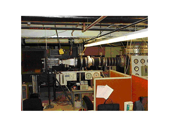 University of Utah Transonic Wind Tunnel (TWT)
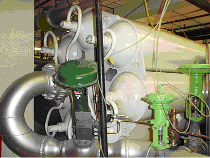 University of Utah Transonic Wind Tunnel Pressure Tanks and Pressure Regulator
Two different test sections are designed to produce Mach numbers, pressure variations, Reynolds numbers, passage mass flow rates, and physical dimensions which match values along turbine blades in operating engines: (i) a non-turning test section with a symmetric airfoil, and (ii) a cascade test section with a cambered turbine blade. On the surface of each of these test blade types, different surface roughness are created to simulate the roughness which exists on operating turbine vanes and blades subject to extended operating times and significant particulate deposition on the surfaces. Different arrangements are used at the inlet of the test section to produce three different levels of mainstream turbulence intensity. Different Freestream Mach numbers are produced by using different total pressure levels at the inlet of test section. Hot-wire anemometry is used for the measurement of inlet turbulence intensity and wake turbulence quantities.
The experimental research includes roughness characterization, aerodynamic loss experiments, surveys of turbulence intensity, length scale values, power spectra, and vortex shedding frequency data, all measured in the wake region downstream of the test blade. Experiments using a symmetric airfoil provide similar suction surface boundary layer development (in the same pressure gradient without flow turning) as exists in operating engines, and is designed to isolate the effects of surface roughness, freestream Mach number, and turbulence intensity on the aerodynamic performance of turbine blades. Experiments in progress using a cambered turbine blade match the geometry and flow conditions, with flow separation and flow turning, as are present in operating engines. Comparison of experimental results from these two different designs will help a better understanding of the flow physics investigated, including the influences of different amount of streamline curvature produced by the airfoil. Cascade test section with a cambered turbine blade.
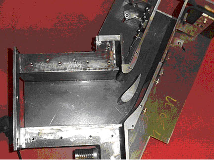
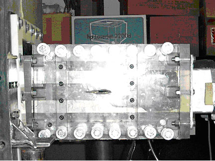
Non-turning test section with a symmetric airfoil
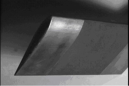
 Symmetric airfoil with simulated rough surface: comprised of bonded nickel particles |
 |
|
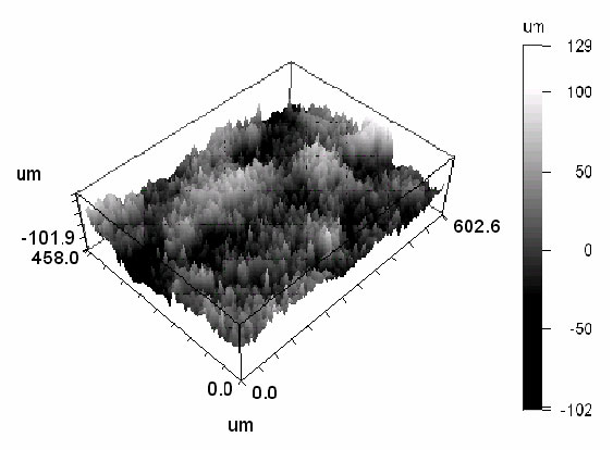
Three-dimensional optical profilometry scan of a simulated rough surface obtained using a Wyko high-resolution optical surface profilometer
|
|
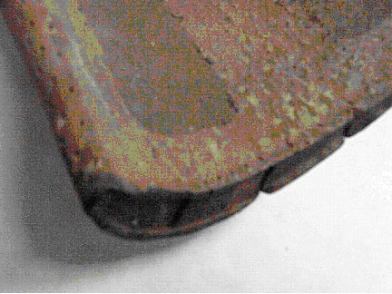 Actual turbine airfoil with roughened surface |
 |
|
Three-dimensional optical profilometry scan of the rough surface from a real turbine blade obtained using a Wyko high-resolution optical surface profilometer
|
|
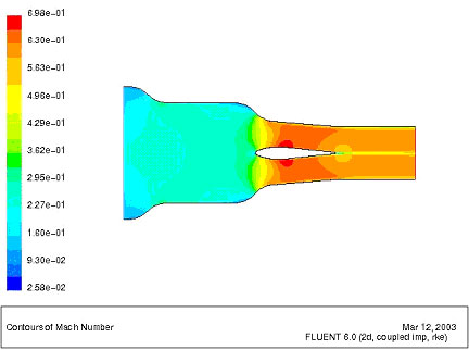
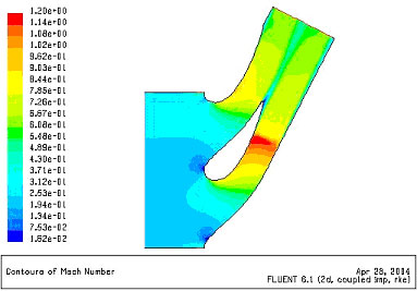
Flow passage Mach number distributions predicted using FLUENT for the non-turning cascade test section, and the cambered cascade test section
REFERENCES:
Transonic Aerodynamic Losses Due to Turbine Airfoil, Suction Surface Film Cooling (D. J. Jackson, K. L. Lee, P. M. Ligrani, and P. D. Johnson), ASME Transactions-Journal of Turbomachinery, Vol. 122, No. 2, pp. 317-326, April 2000.
Determination of Rough-Surface Skin Friction Coefficients from Wake Profile Measurements, (Qiang Zhang, S. W. Lee, and P. M. Ligrani), Experiments in Fluids, Vol. 35, No. 6, pp. 627-635, December 2003.
Effects of Surface Roughness and Turbulence Intensity on the Aerodynamic Losses Produced by the Suction Surface of a Simulated Turbine Airfoil, (Q. Zhang, S. W. Lee, and P. M. Ligrani), ASME Transactions-Journal of Fluids Engineering, Vol. 126, No. 2, pp. 257-265, March 2004.
Effect of Surface Roughness and Freestream Turbulence on the Wake Turbulence Structure of a Symmetric Airfoil (Q. Zhang, S. W. Lee, and P. M. Ligrani), Physics of Fluids, Vol. 16, No. 6, pp. 2044-2053, June 2004.
Mach Number/Surface Roughness Effects on Symmetric Transonic Turbine Airfoil Aerodynamic Losses (Q. Zhang, and P. M. Ligrani), AIAA Journal of Propulsion and Power, Vol. 20, No. 6, pp. 1117-1125, November-December 2004.
Influence of Mach Number and Freestream Turbulence Intensity on the Aerodynamic Losses of a Turbine Vane (Q. Zhang, D. Sandberg, P. M. Ligrani), AIAA Journal of Propulsion and Power, Vol. 21, No. 6, pp. 988-996, November-December 2005.
Numerical Predictions of Stanton Numbers, Skin Friction Coefficients, Aerodynamic Losses, and Reynolds Analogy Behavior for a Transonic Turbine Vane (Q. Zhang, and P. M. Ligrani), Numerical Heat Transfer, Part A: Applications, Vol. 49, No. 3, pp. 237-256, February 2006.
Influence of Surface Roughness On the Aerodynamic Losses of a Turbine Vane (Q. Zhang, M. Goodro, P. M. Ligrani, R. Trindade, S. Sreekanth), ASME Transactions-Journal of Fluids Engineering, Vol. 128, No. 3, pp. 568-578, May 2006.
Aerodynamic Losses of a Cambered Turbine Vane: Influences of Surface Roughness and Freestream Turbulence Intensity (Q. Zhang, and P. M. Ligrani), ASME Transactions-Journal of Turbomachinery, Vol. 128, No. 3, pp. 536-546, July 2006.
Wake Turbulence Structure Downstream of a Cambered Airfoil In Transonic Flow: Effects of Surface Roughness and Freestream Turbulence Intensity (Q. Zhang, and P. M. Ligrani), International Journal of Rotating Machinery, Vol. 2006, ID: 60234, pp. 1-12, July 2006.
Aerodynamic Performance of Suction-Side Gill Region Film Cooling (J. C. Chappell, P. M. Ligrani, S. Sreekanth, T. Lucas, and E. Vlasic), ASME Transactions-Journal of Turbomachinery, Vol. 132, No. 3, pp. 031020-1 to 031020-11, July 2010.
Suction Side Gill Region Film Cooling: Effects of Hole Shape and Orientation on Adiabatic Effectiveness and Heat Transfer Coefficient (J. C. Chappell, P. M. Ligrani, S. Sreekanth, and T. Lucas), ASME Transactions-Journal of Turbomachinery, Vol. 132, No. 3, pp. 031022-1 to 031022-11, July 2010.
Aerodynamic Losses in Turbines With and Without Film Cooling, as Influenced by Mainstream Turbulence, Surface Roughness, Airfoil Shape, and Mach Number (P. M. Ligrani), International Journal of Rotating Machinery, Vol. 2012, Article ID 957421, pp. 957421-1 to 957421-28, (doi:10.1155/2012/957421), 2012.
Second Law Analysis of Aerodynamic Losses: Results for a Cambered Vane With and Without Film Cooling (P. M. Ligrani, and J. S. Jin), ASME Transactions-Journal of Turbomachinery, Vol. 135, No. 4, pp. 041013-1 to 041013-14, July 2013.
Endwall Aerodynamic Losses From Turbine Components Within Gas Turbine Engines (P. M. Ligrani, G. Potts, and A. Fatemi), Propulsion and Power Research, Vol. 6, No. 1, pp. 1-14, March 2017.
Numerical Second Law Analysis Around a Turbine Guide Vane Using a Two-Equation Turbulence Model and Comparison With Experiments (S. Winkler, E. Kerber, T. Hitz, B. Weigand, and P. M. Ligrani), International Journal of Thermal Sciences, Vol. 116, pp. 91-102, June 2017.