– Impingement Cooling
– Impingement Jet Array Heat Transfer With Surface Textures
– Surface Roughness Characterization and Analysis
– Dimple Surface Arrays
– Swirl Chambers
– Surface Heat Transfer Augmentation Within Internal Passages
– Film Cooling
– Full-Coverage Film Cooling
– Double Wall Cooling
– Second Law Analysis of Film Cooling
– Aerodynamic Losses From Turbine Airfoils
– Transonic Turbine Blade Tips
– Transonic Turbine Blade Tips With Film Cooling
– Transonic Turbine Alloy Blades
– Supersonic Flow Experimental Results
– Shock Wave Unsteady Interactions
– Viscous Dissipation Within a Transonic Flow Environment
– Transitional Flows in Curved Channels
– Dean Flow Dynamics in Low-Aspect Ratio Spiral Microchannels
– Unsteady Laminar Impinging Slot Jets
– Electronics Cooling
– Miniature and Micro-Scale Pumps
– Slip Rarefaction Phenomena
– Elastic Instabilities
– Buoyancy-Driven Continuous SPLITT Fractionation
ELECTRONICS COOLING
Electronics Cooling
- Improved heat sinks with larger heat transfer augmentations.
- Use of dimpled surfaces along with other heat transfer augmentation devices.
- Use of dimples on the surfaces of micro-scale passages.
- Jet impingement cooling of a chip equipped with a single cylindrical pedestal profile fin.
- Jet impingement cooling of chips equipped with multiple cylindrical pedestal profile fins.
Jet Impingement Cooling of Chips Equipped with a Single Cylindrical Pedestal Profile Fin
Continued miniaturization of integrated chips is a consequence of recent developments in semiconductor technology and integrated circuit manufacturing methods. As a result, electronic components are packaged to operate at heat flux generation levels and power dissipation levels which are higher than used in the past. One way that this occurs is by placing transistors in closer proximity to each other. With such an arrangement, chip heat flux magnitudes exceed 50 W/cm 2 , but are expected to reach as high as 250 W/cm 2 in the near future. With such flux levels, maintaining acceptable chip temperatures is vital if the high costs of electronic components failures due to the resulting high temperatures are to be avoided. Consequently, chip cooling is a critical factor for the miniaturization of integrated chips and the proper operation of the electronic components, and much new effort is devoted to the search for better ways to manage thermal dissipation.
Impinging jets are simple and efficient devices which can be used to remove heat from surfaces with different-attached component shapes. Some of the earliest investigations regarding the use of impinging jets for cooling of electronic components are described by Sparrow and Larson, and Wadsworth . These investigators describe the use of this technique on protruding fins and other types of protruding-object-extended-surfaces with different shapes. According to these and other investigators, such devices are employed for cooling components in large computer systems such as the IBM-4381, the Fujitsu FACOM M-780, and the Fujitsu VP2000. Although excellent cooling using impinging jets is demonstrated by these studies, only a few other papers address the use of impinging jets for cooling protruding objects. Only two of these are known which address the use of impinging jets to alter surface heat transfer rates on cylindrical pedestals mounted on flat plates.
The present investigations underway at the Univerisity of Utah are focused on providing additional data in this area, especially regarding the dependence of surface heat transfer distributions on the geometric characteristics and orientations of cylindrical pedestal chip components. For the parts of the study described here, both heat transfer and fluid flow data are provided for a single cylindrical pedestal mounted on a flat plate with a turbulent impinging air jet. Such data are needed before effects of impinging jets onto an array of pedestals can be understood. Note that present data can be extended to pedestals with other cross-sections (i.e. elliptical, square) using the cross-sectional equivalent hydraulic diameter as the length scale instead of D . T hermochromic liquid crystals and shroud-transient techniques are used to measure spatially-resolved surface temperature distributions, which are used to deduce local Nusselt numbers . The jet Reynolds number Re in the experiments is 23,000, the dimensionless nozzle-to-surface distance L/d ranges from 2 to 10, and the dimensionless pedestal height H/Dvalues are 0.0 and 1.0.
Figure 1a sh ows a schematic diagram of the test model, which consists of a 35 cm × 35 cm × 1 cm acrylic flat plate, a glass plate, and a cylindrical pedestal. Test model geometric parameters are shown in Fig. 1b. Three different cylindrical pedestals are employed in the study, each with a diameter of D of 2.15 cm, and heights H of 0 cm, and 2.15 cm. When employed, the pedestal is mounted on the acrylic flat plate so that the cylindrical side is perpendicular to the test surface. Flat black paint is used to cover the entire model test surface. Using a spray air brush, the flat plate surface and the pedestals are then coated with micro-encapsulated thermochromic liquid crystals.
Figures 2a and 2b show the variations of wall pressure coefficients along the flat plate for Re = 23,000, and L / d =2-10. H / D = 0 data with no pedestal are given in part a, and H / D =1.0 with pedestal are given in part b. Figure 2b shows that wall pressure coefficients C p gradually decrease with r / d along the upper surface of the pedestal as the jet impinges near the stagnation region. C p values then suddenly increase when fluid streamlines separate from the pedestal, and then collide and reattach with the flat plate surface, which is some distance from the stagnation region. As r/d increases further from about 1.7, C p then gradually drops. C p values then remain nearly constant beyond r/d =2.5 as the boundary layer develops along the flat plate surface downstream of the reattachment region.
Figure 3 shows a visualization of the flow pattern which forms along the flat surface and around the pedestal for H / D of 1.0. These data are given for L/d =2 and Re =2,300. When the flow moves around the pedestal, a fairly large vortex is generated between the side of pedestal and the flat plate because of the flow which separates near the top corner of the cylindrical pedestal, and then forms into a recirculation zone. The strength and placement of such vortices are tied to the magnitude of the secondary pressure coefficient C p maxima, described earlier, which are present nea r r / d =1.8-2.0. Note that the sizes and shapes of the vortices in Fig. 3 for H / D =1.0 are different from the near-pedestal vortices which are present for H / D =0.5. In particular, the vortex size for H / D = 1.0 is naturally bigger than the size associated with H / D= 0.5 because of a higher pedestal.
Figure 4 gives local Nusselt number distributions on the upper surface of the pedestal and along the flat plate for Re =23,000, L / d =2-10. H / D =0 data with no pedestal are given in part a, and H / D =1.0 with pedestal are given in part b. Figure 4b shows that local Nusselt numbers drastically increase with a radial distance away from the stagnation point on top of the pedestal for an H/D value of 1.0. These are partially due to the small flow re-circulation zones present on top of the pedestal, as well as flow mixing associated with the separation of flow streamlines near the edge of the upper surface on the pedestal. Figure 4b also shows that local Nusselt numbers drastically increase with r/d over r/d ranging from 0.7 to 1.5-1.6 because of shear layer reattachment and the circulation of the vortices which form next to the pedestal. In general, this increase becomes more pronounced as H/D becomes smaller because of greater vortex influences. The resulting maximum local Nusselt numbers are thus present over different ranges of r/d (which depend upon the H/D value), which range from 1.0 to 2.0.
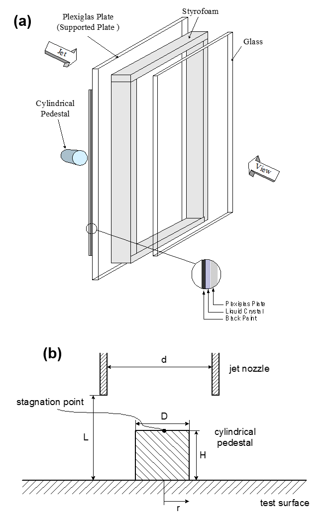
Figure 1: (a) Schematic diagram of test model.
(b) Test model geometric parameters.
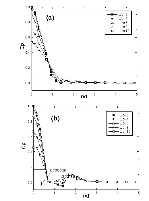
Figure 2. Variation of wall pressure coefficients along the flat plate for Re = 23,000, and L / d =2-10.
(a) H / D = 0 with no pedestal.
(b) H / D =1.0 with pedestal.
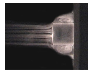
Figure 3. Visualizations of flow patterns along the flat surface and around the pedestal for H / D =1.0, L/d =2, and Re =2,300.
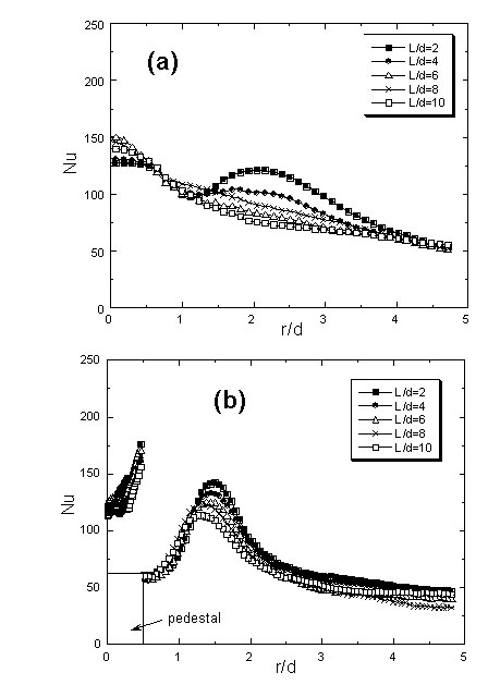
Figure 4. Local Nusselt number distributions on the upper surface of the pedestal and along the flat plate for Re =23,000, L / d =2-10.
(a) H / D =0 with no pedestal.
(b) H / D =1.0 with pedestal.
REFERENCES:
Numerical Simulation of Flow and Heat Transfer Inside a Micro-Channel With One Dimpled Surface, (X. J. Wei, Y. K. Joshi, P. M. Ligrani), Paper IMECE2002-21633, 2002 International Mechanical Engineering Congress and Exhibition (IMECE), New Orleans, Louisiana, November 17-22, 2002.
Jet Impingement Cooling of Chips Equipped With Cylindrical Pedestal Profile Fins (Y. S. Chung, D. H. Lee, and P. M. Ligrani), ASME Transactions-Journal of Electronic Packaging, Vol. 127, No. 2, pp. 106-112, June 2005.
Numerical Simulation of Laminar Flow and Heat Transfer Inside a Micro-Channel With One Dimpled Surface, (X. J. Wei, Y. K. Joshi, P. M. Ligrani), ASME Transactions-Journal of Electronic Packaging, Vol. 129, No. 1, pp. 63-70, March 2007.
Jet Impingement Cooling of Chips Equipped With Multiple Cylindrical Pedestal Fins (D. H. Lee, Y. S. Chung, and P. M. Ligrani), ASME Transactions-Journal of Electronic Packaging, Vol. 129, No. 3, pp. 221-228, September 2007.
Confined, Milliscale Unsteady Laminar Impinging Slot Jets and Surface Nusselt Numbers (D. H. Lee, J. R. Bae, H. J. Park, J. S. Lee, and P. M. Ligrani), International Journal of Heat and Mass Transfer, Vol. 54, Nos. 11-12, pp. 2408-2418, May 2011.
Milliscale Confined Impinging Slot Jets: Laminar Heat Transfer Characteristics for an Isothermal Flat Plate (D. H. Lee, H. J. Park, and P. M. Ligrani), International Journal of Heat and Mass Transfer, Vol. 55, No. 9-10, pp. 2249-2260, April 2012.
Confined, Milliscale Unsteady Laminar Impinging Slot Jets: Effects of Slot Width on Surface Stagnation Point Nusselt Numbers (D. H. Lee, J. R. Bae, M. Ryu, and P. M. Ligrani), ASME Transactions – Journal of Electronic Packaging, Vol. 134, No. 4, pp. 041004-1 to 041004-11, December 2012.
Visualization and Structure of Confined, Milliscale, Unsteady Impinging Slot Jets and Associated Vortices (D. H. Lee, H. J. Park, and P. M. Ligrani), Experiments in Fluids, Vol. 54:1420, pp. 1-15, 2013.