– Impingement Cooling
– Impingement Jet Array Heat Transfer With Surface Textures
– Surface Roughness Characterization and Analysis
– Dimple Surface Arrays
– Swirl Chambers
– Surface Heat Transfer Augmentation Within Internal Passages
– Film Cooling
– Full-Coverage Film Cooling
– Double Wall Cooling
– Second Law Analysis of Film Cooling
– Aerodynamic Losses From Turbine Airfoils
– Transonic Turbine Blade Tips
– Transonic Turbine Blade Tips With Film Cooling
– Transonic Turbine Alloy Blades
– Supersonic Flow Experimental Results
– Shock Wave Unsteady Interactions
– Viscous Dissipation Within a Transonic Flow Environment
– Transitional Flows in Curved Channels
– Dean Flow Dynamics in Low-Aspect Ratio Spiral Microchannels
– Unsteady Laminar Impinging Slot Jets
– Electronics Cooling
– Miniature and Micro-Scale Pumps
– Slip Rarefaction Phenomena
– Elastic Instabilities
– Buoyancy-Driven Continuous SPLITT Fractionation
MINIATURE AND MICRO-SCALE PUMPS
Miniature and Micro-Scale Pumps
- RSP – Rotating Shaft Pumps.
- VDP – Viscous Disk Pumps.
- Osmotic Pumps.
- Pressure and temperature compensation.
- Simplicity of design.
- Constant flow rate pumps.
- Miniature and micro-scale.
- Easy to manufacture.
The area of microfluidics is developing with many new sensors, separation devices, drug delivery systems, and other small-scale and micro-scale fluidic devices. For many of these devices there is a need to circulate or move fluid through macro-scale and micro-scale channels. A variety of micropumps are available to meet this need, generally to fulfill specific applications. These include membrane pumps, electrohydrodynamic (EHD) pumps, electrokinetic (EK) pumps, rotary pumps, peristaltic pumps, phase change pumps, and several other types of pumps. Non-mechanical pumps like the electrohydrodynamic and electrokinetic pumps do not have moving parts, which increases reliability. However, such devices are generally limited by low flow rate and pressure rise capabilities, the applications of the pump, the working fluids that can be pumped, and high supply voltage requirements. Mechanical pumps like rotary pumps, peristaltic pumps, and membrane pumps have a wide variety of possible working fluids and applications. However, such mechanical micro-pumps are believed to be feasible only when they are greater than a certain size, due to the large viscous forces of the fluid for small pump geometries.
Viscous Disk Pumps (VDPs)
The disk pumps developed at the University of Utah are unique because they use the viscous stress to produce a pumping effect by employing one or two disks and a wiper to force fluid through a passage. The two axially collinear disks, or the disk and the top pump housing, are separated by a small gap. The wiper is situated between the spinning disk(s). Figure 1 shows a cross-sectional view of the disk pumps. The spinning of the disk(s) cause a net movement of fluid due to the viscosity of the fluid, and the transfer of momentum from the disks to the fluid. The wiper acts to “wipe” the fluid off the disk(s), and to direct the fluid into the outlet channel. Fig. 2 shows the movement of the fluid through the single-disk pump as indicated by the small arrows. The advantages of this micropump compared to other micropumps include a wide range of possible flow rates, simplicity, constant flow, planar structure, well controlled flow rate, and possible mixing characteristics. Figure 3 shows an exploded view of the double-disk assembly. Figure 4 shows the double-disk pump assembly with the top housing partially removed. The disk diameter in Fig. 4 is 2.381 mm. The maximum flow rate achieved is 0.74 ml/min and 2.1 ml/min for the single-disk and double-disk pumps, respectively, with a disk radius of 2.381 mm, gap height of 103 µm, and rotational speed of 5000 rpm. Figure 5 shows variations of flow rate with rotational speed of the disk pumps.
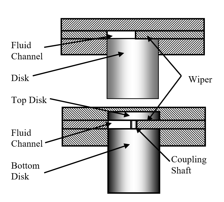 |
Figure 1. Cross-sectional view of the single-disk and double-disk pumps. |
|---|---|
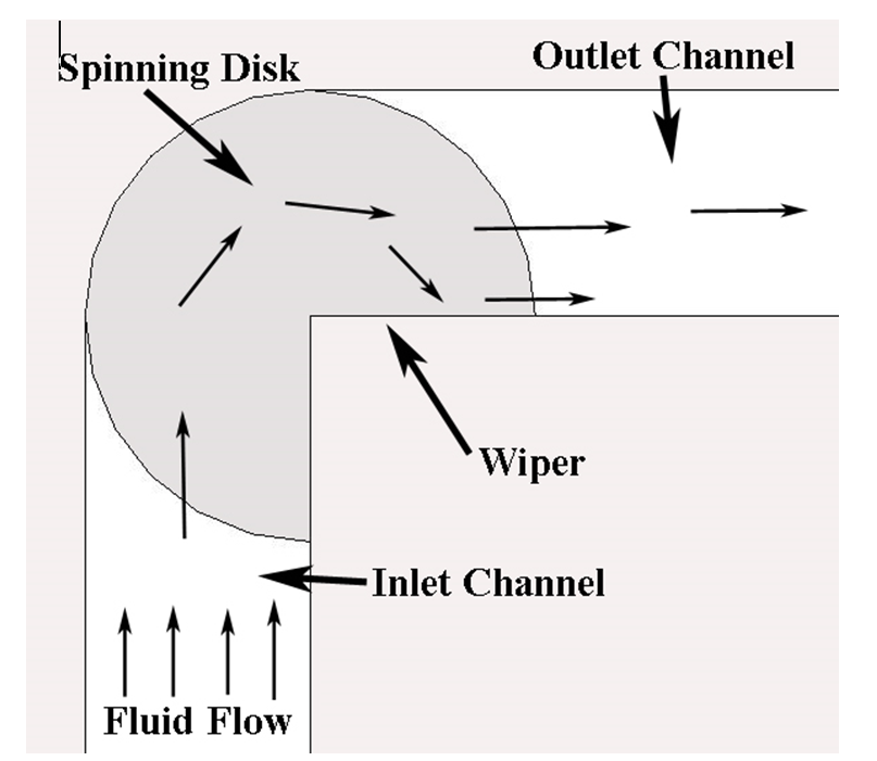 |
Figure 2. Top view of the single-disk pump. Arrows indicate flow direction. Disk rotates clock-wise. |
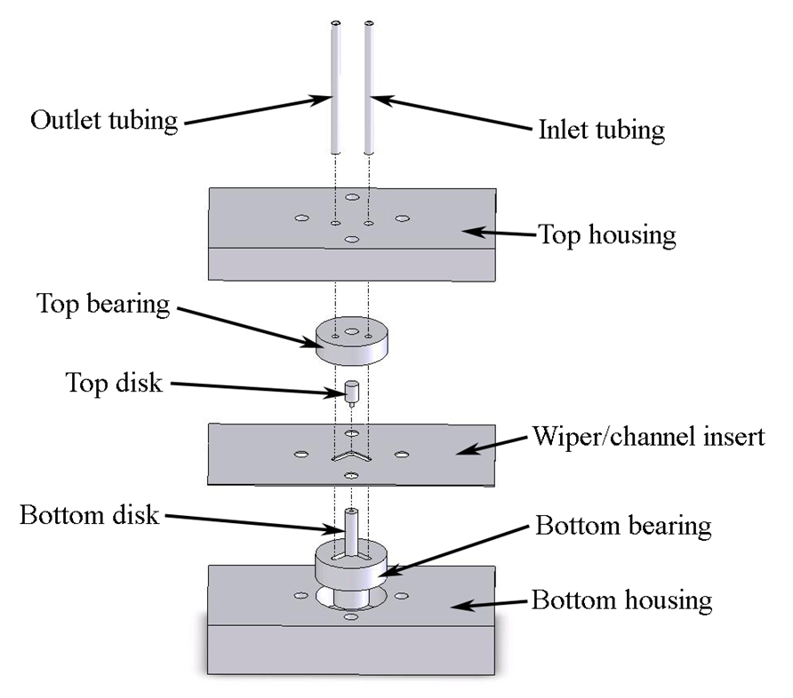 |
Figure 3. Exploded view of the double-disk pump assembly. |
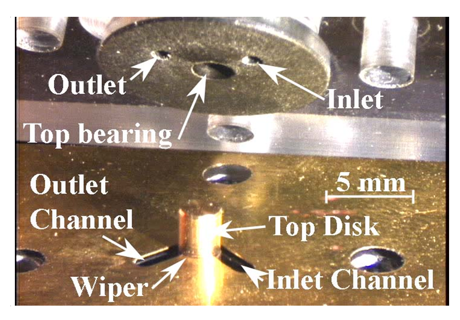 |
Figure 4. Double-disk pump assembly. |
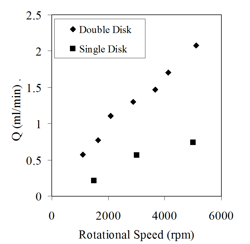 |
Figure 5. Flow rates and rotational speeds for the disk pumps from experimental testing, and scale analysis. Disk diameter = 2.38 mm, gap height = 103 µm. |
Rotary Shaft Pumps (RSPs)
Another motivation of the present effort is to demonstrate the operation and feasibility of a millimeter-scale pump which imposes fluid motion and pressure rise by means of viscous and inertial forces. The behavior and performance of macro-scale centrifugal pumps are well established and well known. However, the dynamics, performance, and efficiency of centrifugal pumps change as the size of the pump is altered. For example, secondary flows, and the losses associated with them, become more important as macro-scale impeller passage size decreases. As size decreases further, surface (viscous) forces become more significant, and can dominate the performance of the pump.
One important dimension of many centrifugal pumps is the gap distance between the top of the blades, and the pump housing. As the gap increases, there is more leakage across blades, and the overall hydraulic efficiency of the pump decreases. If the gap is too small or zero, the blades can be damaged by contacting the pump housing. On a macro-scale this “gap problem” is generally insignificant, but on a micro-scale, or a millimeter-scale, the gap between the top of the blades and the pump housing can be about the same as the height of the impeller blades.
The design of the rotary shaft pump (RSP) eliminates this “gap problem.” The RSP impeller is constructed by boring a hole in the end of a shaft, and then cutting slots in the side of the shaft at the bottom of the bored hole, as shown in Figure 6 which presents a cutaway view of the RSP impeller. Figure 7 shows a stainless steel RSP impeller next to an American quarter. Thus, the metal between the slots acts as the blades of the impeller, and the slots form passages between the bored interior and outer shaft surface. The gap at the top of the blades is zero, because the top of the blades also connect to the shaft. The hollow interior of the RSP transfers momentum to the passing fluid through viscous forces. This “pre-swirl” can be significant on a millimeter-scale or micrometer-scale, when the ratio of the hollow interior length to diameter is large, and the circumferential wall velocity is greater than the average axial fluid velocity. The “pre-swirl” aids in the overall fluid pumping by reducing the sudden acceleration of the fluid at the inner blade tip, and by reducing the extent of separated flow as it approaches the slots.
The rotating shaft is mounted using bearings located above and below the exit plenum, which are mounted in the pump housing. The volute and an outlet channel are then located in the region between the upper and lower bearings and pump housing, as seen in Figure 8. The water reservoir is connected to the pump housing by a plastic tube with an inner diameter of 4.5 mm and a length of 381 mm. This plastic tube is press fit into the inlet channel as shown in Figure 8. There is a continuous channel, from the inlet tubing, through the pump housing and top of the upper bearing to the inlet of the RSP. Inside the channel through the upper bearing, the fluid flow transitions from a non-rotating bearing wall to the inside of a rotating shaft. The bearing forms a seal for the spinning shaft of the RSP, which reduces the leakage from the impeller outlet to the shaft inlet of the RSP. The side walls of the volute and part of the outlet channel are formed by a piece of machined brass shim stock that is 416 µm tall. This volute and outlet channel are aligned with the slot ports of the shaft. With this construction, when the shaft spins, centrifugal, viscous, and inertial forces from the spinning impeller shaft force fluid flow through the shaft inlet, through the interior of the shaft, through the slots, out through the slot ports, into the volute, and then into and through the outlet channel, as shown by the arrows in Figure 8. The volute design employed for the present investigation, to minimize the effects of surface forces, is called the open volute design. The open volute design is characterized by a large “open” channel from the impeller to the exit plenum, as shown in Figure 10.
One of the purposes of a volute is to efficiently direct fluid toward the outlet channel. The volute designs employed in macroscale pumps, where fluid motion is induced by inertial forces, are different from the design employed here. This design difference is because flow from the impeller exit and within the volute is significantly influenced by both inertial forces and surface forces. The present open volute design increases the width and maximizes the hydraulic diameter thereby decreasing the average fluid velocity and velocity gradients, which also reduces viscous losses.
The maximum flow rate and pressure rise for the RSP pump is achieved with the 4-blade backward-curved impeller, with a maximum flow rate of 64 ml/min, and maximum pressure rise of 2.1 kPa. Figure 9 shows the flow rate and pressure rise characteristics of this particular RSP.
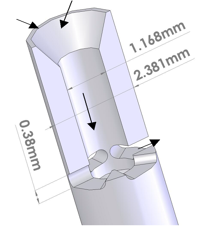 |
Figure 6. Cutaway view of the rotary shaft pump (RSP) assembly. |
|---|---|
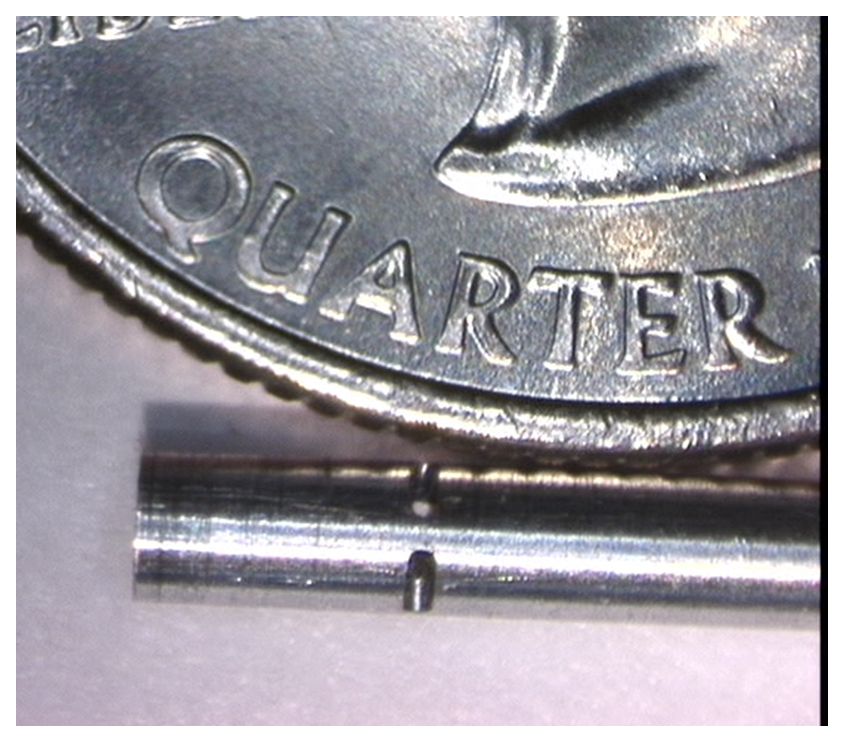 |
Figure 7. RSP impeller next to an American quarter. Impeller diameter is 2.381 mm. |
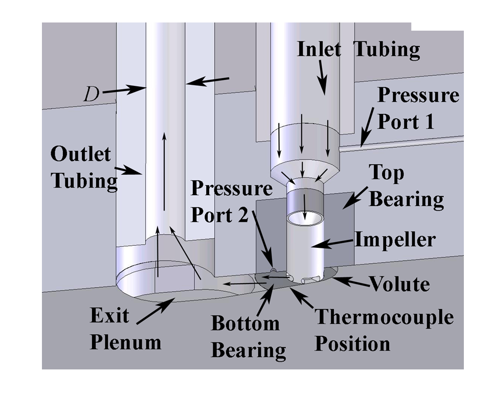 |
Figure 8. Cutaway view of the rotary shaft pump (RSP) assembly. |
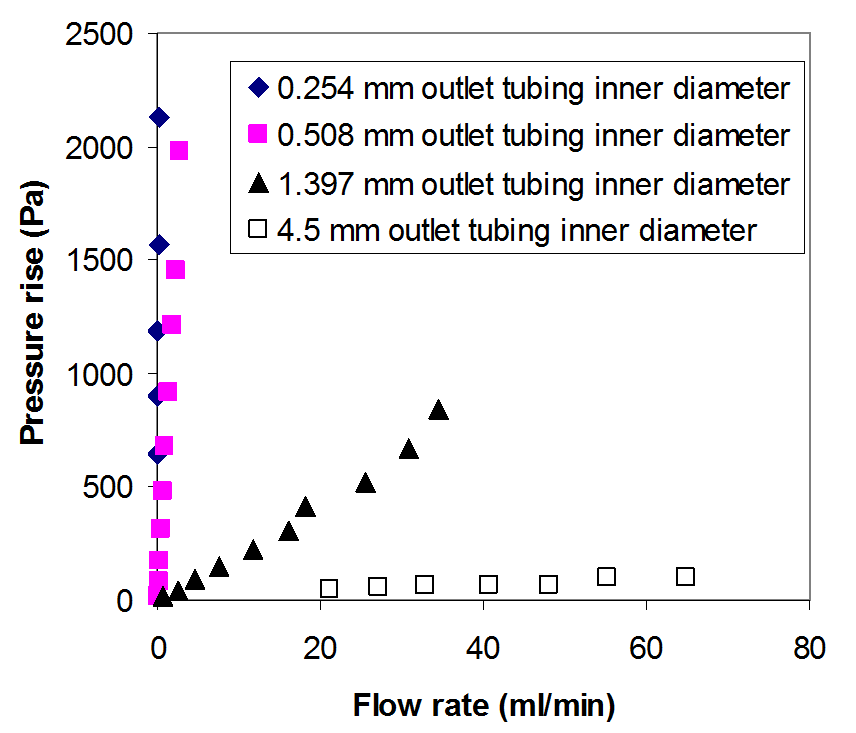 |
Figure 9. Pressure rise and flow rate characteristics of the 2.381 diameter, 4-blade backward-curved impeller. |
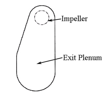 |
Figure 10. Open volute configuration. |
REFERENCES:
Single-Disk and Double-Disk Viscous Micropumps, (D. B. Blanchard, P. M. Ligrani, and B. K. Gale), Sensors and Actuators A: Physical, Vol. 122, No. 1, pp. 149-158, July 2005.
Performance and Development of a Miniature Rotating Shaft Pump (RSP), (D. B. Blanchard, P. M. Ligrani, and B. K. Gale), ASME Transactions-Journal of Fluids Engineering, Vol. 127, No. 4, pp. 752-760, July 2005.
Comparisons of Different Viscous Pumps Based on Physical Flow Behavior (D. B. Blanchard, and P. M. Ligrani), Sensors and Actuators A: Physical, Vol. 126, No. 1, pp. 83-92, January 2006.
Miniature Single-Disk Viscous Pump (Single-DVP), Performance Characterization (D. B. Blanchard, P. M. Ligrani, and B. K. Gale), ASME Transactions-Journal of Fluids Engineering, Vol. 128, No. 3, pp. 602-610, May 2006.
Optimization of an Innovative Rotary Shaft Pump (RSP) (J. Allen, and P. M. Ligrani), ASME Transactions-Journal of Fluids Engineering, Vol. 128, No. 6, pp. 1281-1288, November 2006.
Micro-Scale and Millimeter-Scale Rotating Disk Couette Flows, Experiments and Analysis (D. B. Blanchard, and P. M. Ligrani), Experiments in Fluids, Vol. 41, No. 6, pp. 893-903, December 2006.
Osmotic Dispense Pump For Operation at Different Temperatures and Pressures (T. Deem, P. M. Ligrani, D. Tower, and J. Connelly), Sensors and Actuators A: Physical, Vol. 136, No. 2, pp. 742-748, May 2007.
Slip and Accommodation Coefficients From Rarefaction and Roughness in Rotating Microscale Disk Flows, (D. B. Blanchard, and P. M. Ligrani), Physics of Fluids, Vol. 19, No. 6, Article No. 063602, June 2007.
Microscale Disk Induced Gas Displacement With and Without Slip (D. B. Blanchard, and P. M. Ligrani), Journal of Micromechanics and Microengineering, Vol. 17, No. 10, pp. 2108-2117, October 2007.
Slip Due to Surface Roughness for a Newtonian Liquid in a Viscous Micro-Scale Disk Pump (P. M. Ligrani, D. Blanchard, and B. Gale), Physics of Fluids, Vol. 22, No. 5, pp. 052002-1 to 052002-15, May 2010.
Deviations Due To Non-Newtonian Influences Within a Miniature Viscous Disk Pump (P. M. Ligrani, H. Jiang, B. Lund, and J. S. Jin), ASME Transactions-Journal of Fluids Engineering, Vol. 135, No. 3, pp. 031205-1 to 031205-12, March 2013.
Development and Control of Elastic Turbulence Within a Micro-Scale Viscous Disk Pump (B. Lund, P. M. Ligrani, and M. Brown), Advances and Applications in Fluid Mechanics Journal, Vo. 19, No. 3, pp. 517-539, August 2016.
Miniature Viscous Disk Pump: Performance Variations From Non-Newtonian Elastic Turbulence (P. M. Ligrani, B. Lund, and A. Fatemi), ASME Transactions-Journal of Fluids Engineering, Vol. 139, No. 2, pp.021104-01 to 021104-10, February 2017.
Elastic Turbulence Influences and Convective Heat Transfer Within a Miniature Viscous Disk Pump (D. Copeland, C. Ren, M. Su, and P. M. Ligrani), International Journal of Heat and Mass Transfer, Vol. 108, Part B, pp. 1764-1774, May 2017.